How to choose the right furnace for tempering and annealing III

In this section, we will focus on the energy consumption of annealing and tempering furnaces.
There are a large number of different designs of tempering or annealing equipment. Devices can be chamber, shaft, continuous, with Class A, B and C atmospheres. They can also be multi-purpose, usually in combination with diffuse processes such as gas nitrocarburizing, nitriding or under reduced pressure (LPN). The devices can also be vacuumable, or work directly as fully vacuum ovens (Fig. 1).
![]()
Fig. 1 – Different types of furnaces for tempering and annealing
Furnaces can be of various sizes, from small chamber furnaces to huge wagon furnaces. Furnaces can be heated with electricity or natural gas. However, a gas-fired furnace can almost certainly be excluded for commercial heat treatment plants due to excessive CO2 emissions after 2027. It can be assumed that it is during this period that emissions from the energy mix will drop below the value of emissions from natural gas (Fig. 2). With accounting depreciation of furnaces for 20 years, we cannot risk being exposed to additional taxes in terms of CO2 production.
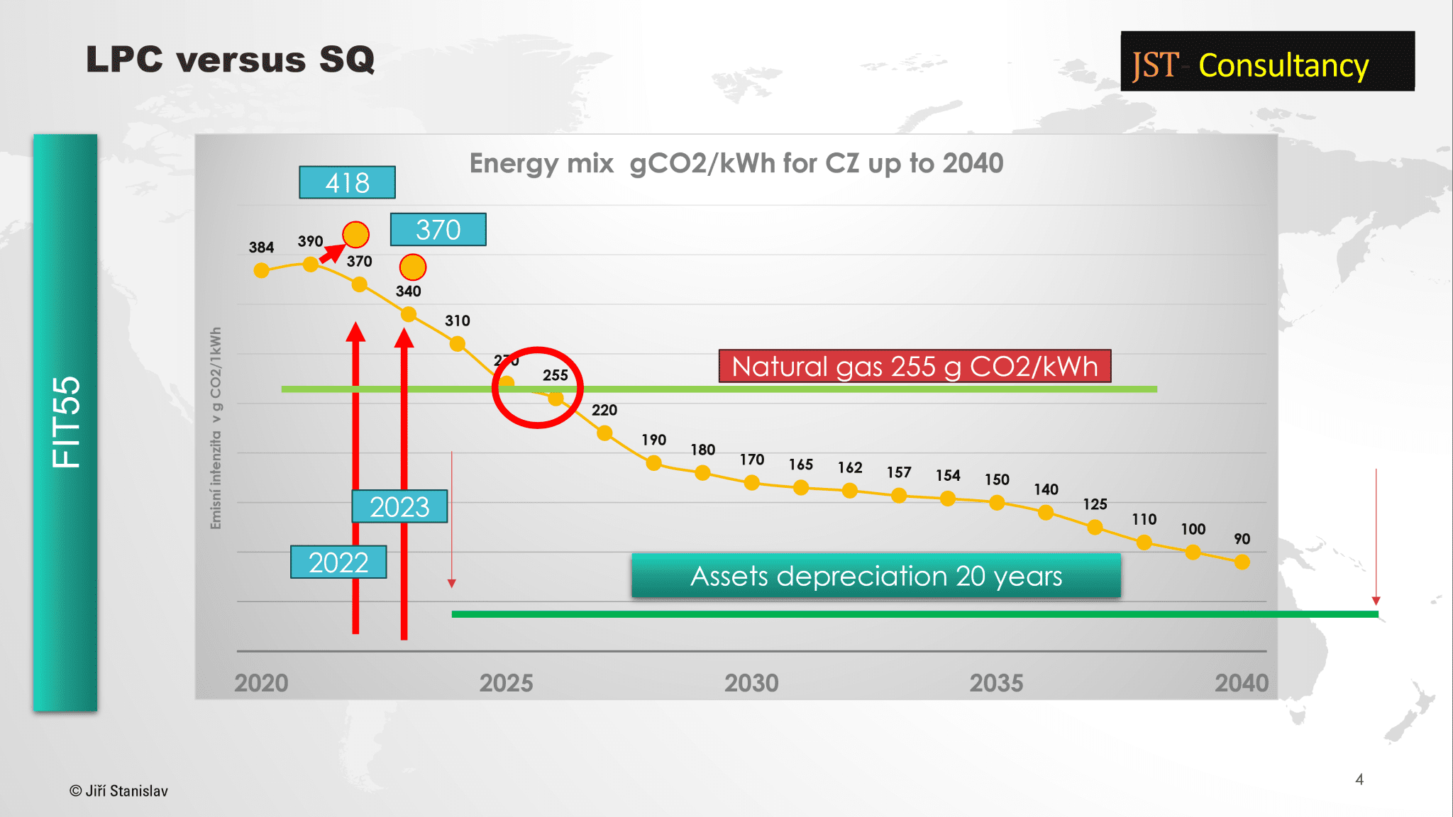
- Fig. 2 – Expected development of the energy mix in CZ until 2040
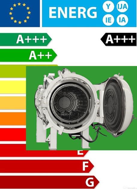
- Fig. 3 – A typical energy label for household appliances
But what about consumption? If we go to buy a refrigerator or a washing machine, we have an energy label on it showing that the device works in class A+++ for example. But what about devices for heat treatment, where the importance of this parameter is much greater than in the case of a refrigerator?
When investing in a new device, we usually find out from the offer what the total input power of the furnace is, sometimes also information is added about the input power of the cooling turbines, circulation fan or vacuum pumps, power input for heating the oil bath, etc. But these are the data we need for dimensioning of the cross-section of the supply cable or circuit breakers and fuses.
However, we usually do not receive any information about actual consumption. And when we ask about it, we usually get strange information from oven manufacturers, usually testifying to their detachment from reality. At the same time, e.g. in a well-managed heat treatment operation, one of the KPI indicators is the amount of sales per 1 KWh of energy consumed, or energy consumption per 1 kg of product, or to calculate the costs of the quotation process, we need to know at least the average consumption of the equipment so that we can calculate the project costs of cycle and subsequently set the offer price to the customer.
However, since oven manufacturers are not yet able to supply equipment with an energy label, our choice will be based only on tests and experience. In general, however, we should aim for a parameter of consumption per 1 kg of batch with values of 0.5 to 0.7 kWh/kg. These are achievable, but usually only for a certain type of furnace design and batch structure.
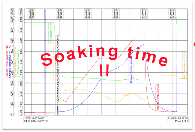
In order to even begin, we need to measure our consumption here. So, the first step is to order a furnace that has consumption measurement. We can be satisfied with the total consumption, or we can also have a partial measurement for the heating, fan, vacuum pump, etc.
- Fig. 4 – Energy consumption measurement
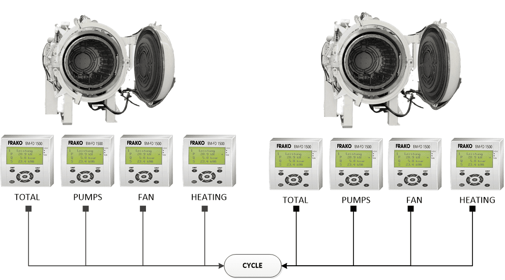
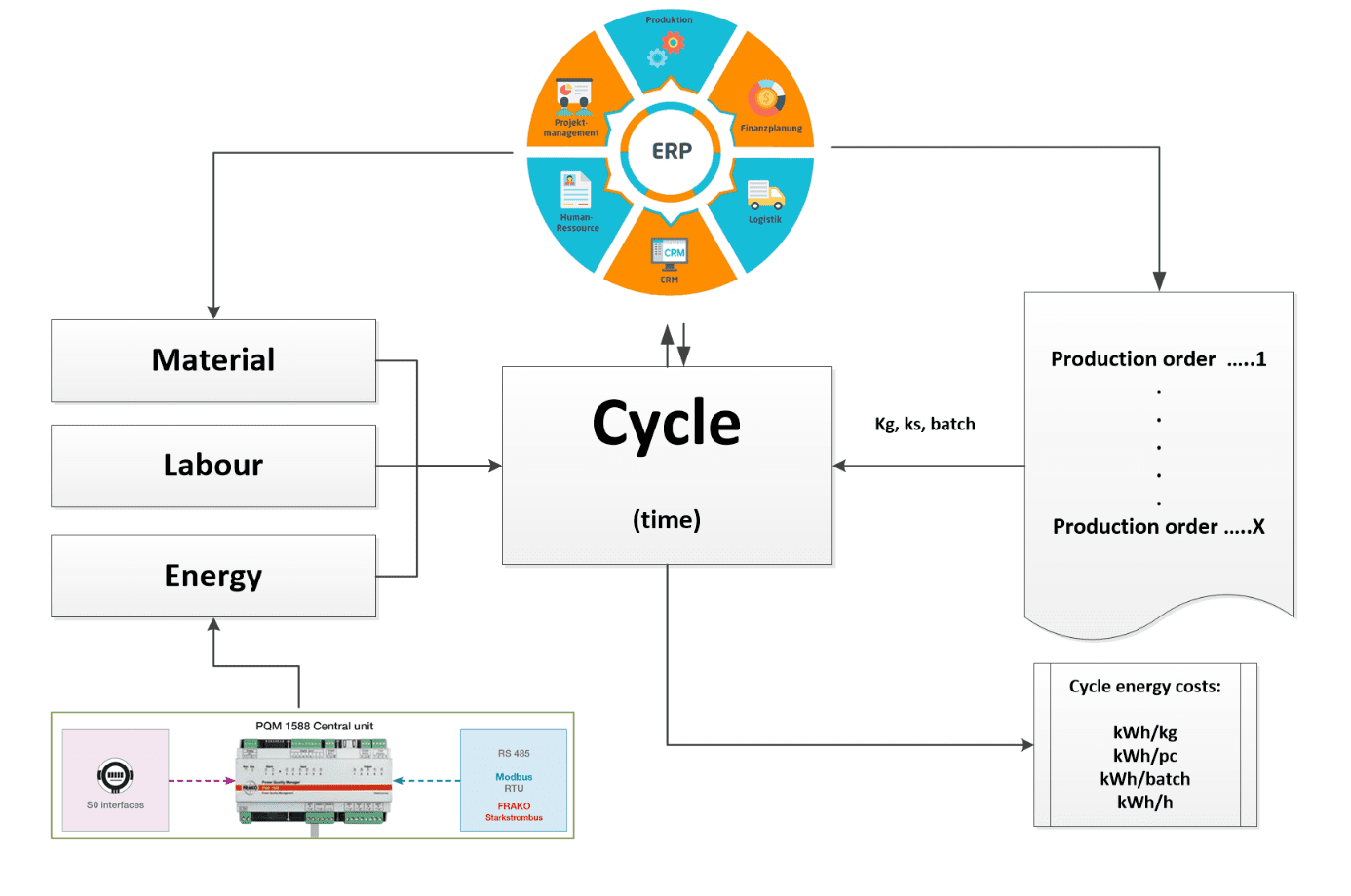
- Fig. 5 – Design of connection of the furnace with the ERP system and monitoring of costs per cycle
Since we need to know the consumption per production cycle, the furnace must be able to assign the consumed kWh to the cycle ID. The cycle ID identifies what we did in the furnace. This is worse, because in order to calculate the KPI for energy consumption per 1 kg of batch, we need to know how many kg we processed in the cycle. But the furnace doesn’t know that anymore, so it is necessary to build a connection between the furnace and the ERP system. There are more solutions, but I won’t describe them anymore. That’s up to the investor. As a guide, we can proceed from Fig. 5.
But for our purposes, the energy concept of the furnace is important. It should ensure that the maximum input energy is transferred to the load. This is a problem with gas-fired furnaces, because 30% of the input energy goes into the flue gas. Thus, if an electrically heated furnace for annealing and tempering has an efficiency of 66%, then a gas-heated furnace will have an efficiency of only 46%.
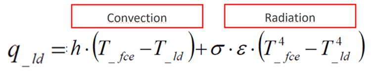
In order for the energy transfer to be as efficient as possible, it should combine the radiation component and the convection component as best as possible. But since annealing or tempering takes place at low temperatures, usually up to 750 °C, then the radiation component will not be so significant. So, we will have to put the accent on the convection component. The formula for the heat flux density is as follows:
where:
- q_ld specific heat flow (W/m2)
- Tfce – furnace temperature (°C)
- Tld – load surface temperature
- h – heat transfer coefficient (W/m-2K-1)
- σ – Stefan-Boltzmanova constant (5,67 * 10-8 W/m-2K-4)
- ԑ – surface emissivity
The difference in the efficiency of radiation heat flow can be seen in Fig. 6. When placing a cold batch in a furnace heated to 450 °C, the heat flow from radiation is 5% of the heat flow that we would obtain by placing it in a furnace heated to 950 °C.
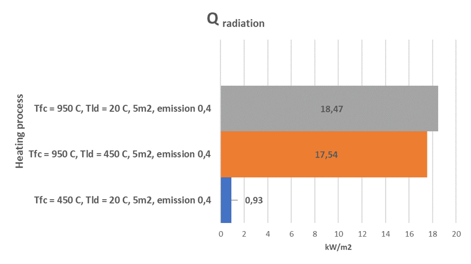
Fig. 6 – Comparison of the heat flow between the furnace temperature and the load at an emissivity of 0.4 a) when placing in a furnace heated to 950 °C, b) when placing a load preheated to 450 C in a furnace heated to 950 C, c) when preheating the load to 450 °C
To increase the convection component, we need to increase the heat transfer coefficient h. It depends on the type of gas, pressure and velocity. For the type of gas, we are usually limited by the choice between air and nitrogen. Since air is made up mostly of nitrogen, the two atmospheres will be almost identical in terms of their physical behaviour. In practice, however, there may also be a need for an EXO atmosphere, e.g. from split ammonia, ENDO, a mixture of N2+5% H2 or argon.
Since classic furnaces with air or with a protective atmosphere do not have the option of overpressure, then the pressure parameter is practically unchangeable and will be 1 bar abs. The fact that we will have a slight overpressure of nitrogen in the furnace up to 50 mbar due to the backflow of air into the furnace does not play a role.
So, we’re left with gas velocity. But since it depends on the power and type of fan, we have no chance to recognize it before we start using the oven. We just want it to be so high that we have a turbulent flow in the furnace, and at the same time the heat exchange surface between the heated elements and the gas medium is as large as possible. The fact that this may not be the case can be seen in Fig. 7.
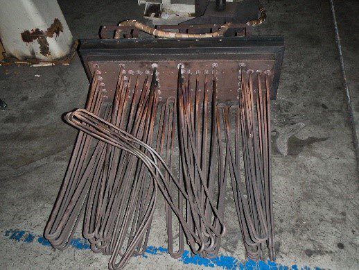
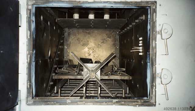
Fig. 7 and 8 – Heating elements of the historic Elterma VDFC vacuum tempering furnace and inner chamber
Although we can purchase furnaces for tempering and annealing only with heating elements built in an insulating lining, most furnaces are equipped with a muffle or a so-called circulating insert. Furnaces with a gas-tight retort are also becoming more and more widespread. Furnaces with a muffle, circulation insert or retort can have heating elements from the outside or from the inside (Fig. 9 and 10).
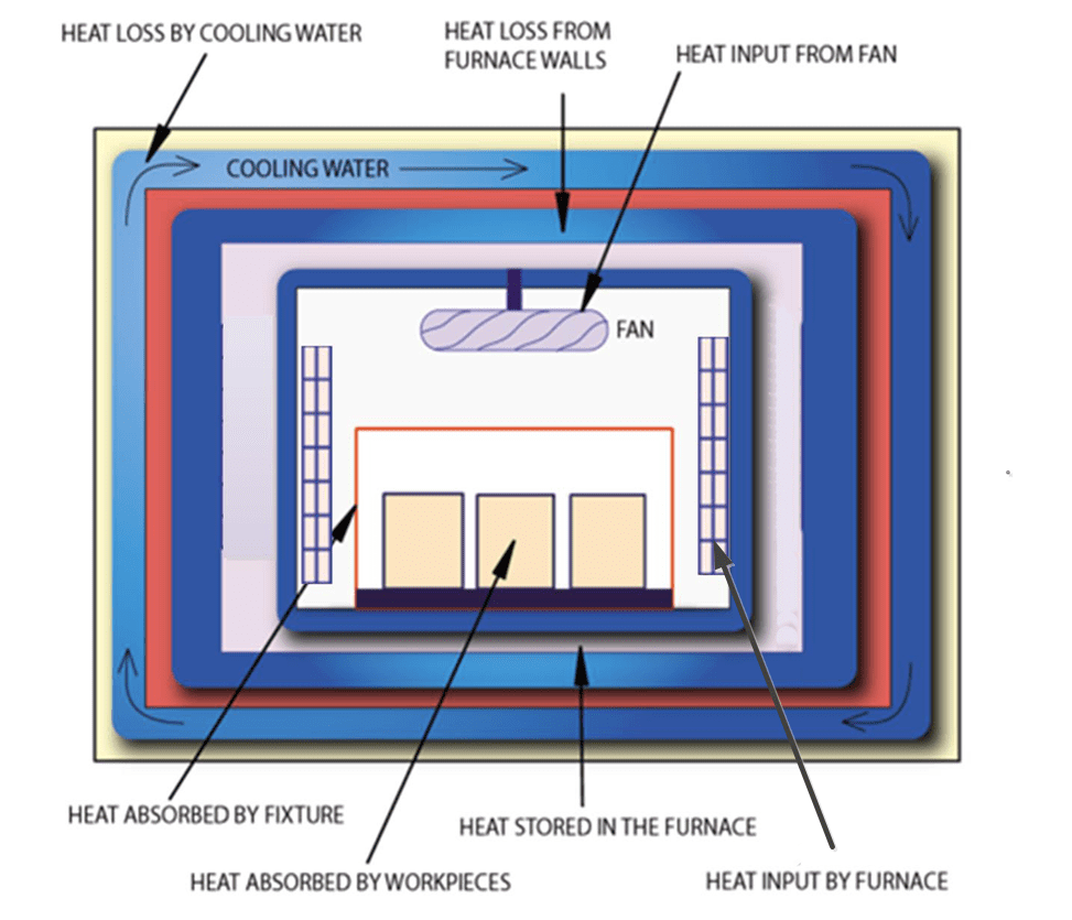
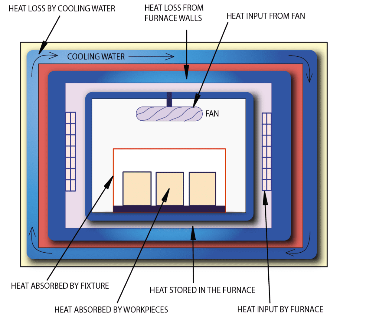
Fig. 9 and 10 – An example of the structural arrangement of a muffle furnace with external and internal heating
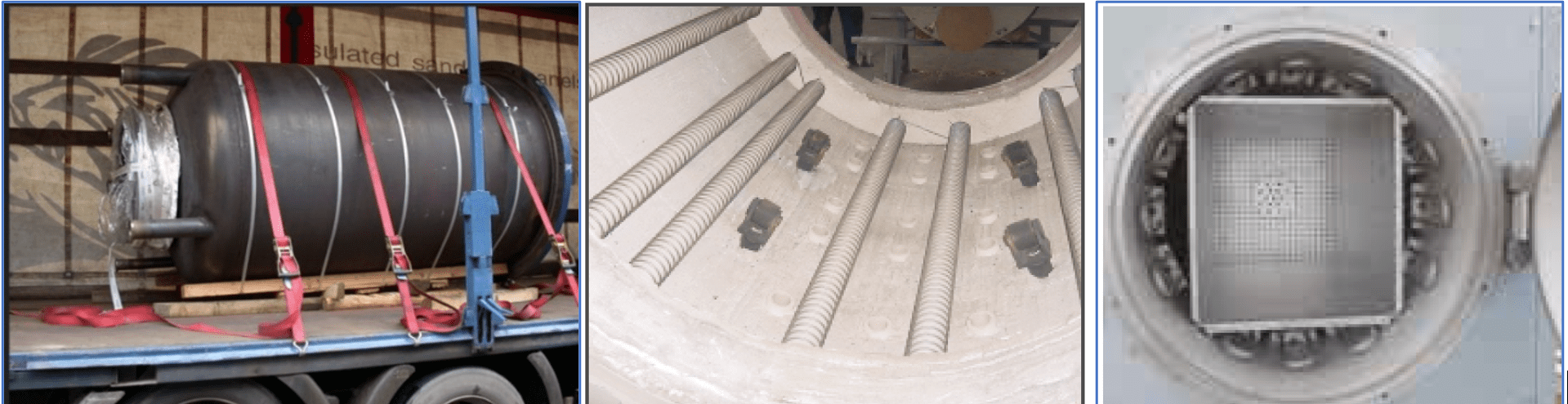
Fig. 11 – a) furnace retort b) heat elements outside of the retort, c) heating elements inside the retort
In the first case, the heating elements transmit part of the heat flow to the muffle, retort or circulation insert, but the same part of heat energy will also act on the opposite side, i.e. to the lining or insulation of the external walls. The radiation component will be almost zero in this case.
In the second case, the heating elements on the one hand heat the gas flowing inside by convection, on the other hand they directly irradiate the surface of the charge and will therefore contribute to the energy balance as well as the second component.
This second option is therefore more effective and efficient in terms of heat transfer. This is particularly evident in vacuum tempering and annealing furnaces with direct heating. A typical representative of this furnace design is the vacuum tempering furnace from TAV Vacuum Furnaces
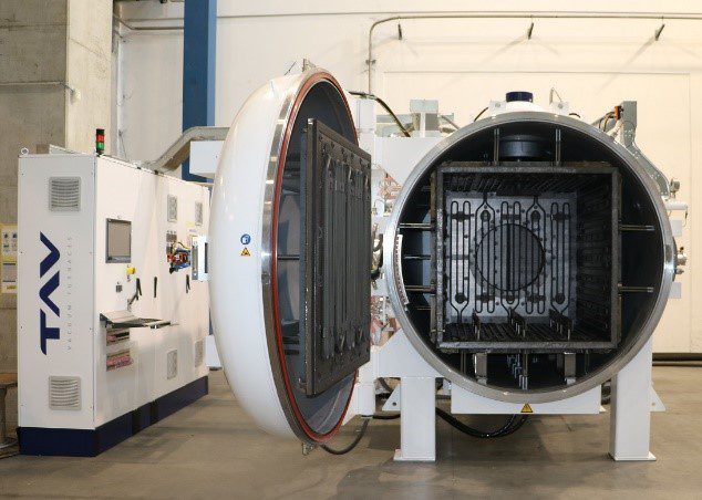
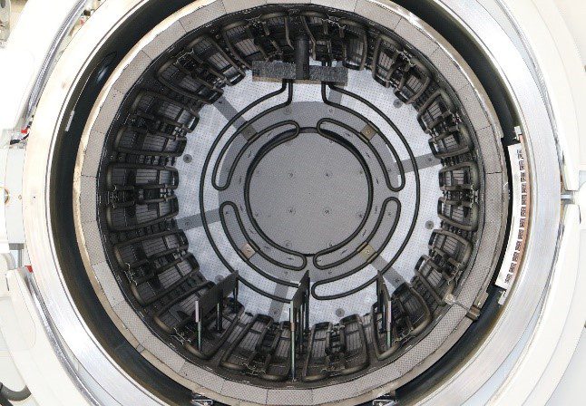
Fig. 12 and 13 – Different variants of the heating chamber of the TAV tempering and annealing furnace
Unlike atmospheric furnaces, with vacuum furnaces we can increase the working pressure. Today, the usual furnace design allows an overpressure of 1 bar, i.e. 2 bar abs.
We have a problem with retort furnaces, because with each cycle we have to heat and cool a retort weighing hundreds of kilograms. The result is shown in Fig. 14. The graph shows that the retort consumes 30 to 40% more energy than the furnace with direct heating. With larger weights and longer cycle times, the difference in consumption decreases, however the curves meet at infinity. Therefore, this type of furnace is advantageous to use for diffusion processes such as nitriding or carbonitriding, which usually have much longer cycle times than tempering processes, but not for tempering or annealing. But there are exceptions.
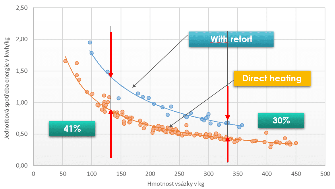
Fig. 14 – Chart comparing energy consumption at retort furnace and directly heated furnace
An important factor in the energy balance of the furnace is thermal insulation. This will determine how much heat we use to heat the batch, and how much heat will be removed from the furnace through losses. What characteristics should it have? Minimum thermal capacity, minimal expansion, low thermal conductivity, resistance to flowing gas.
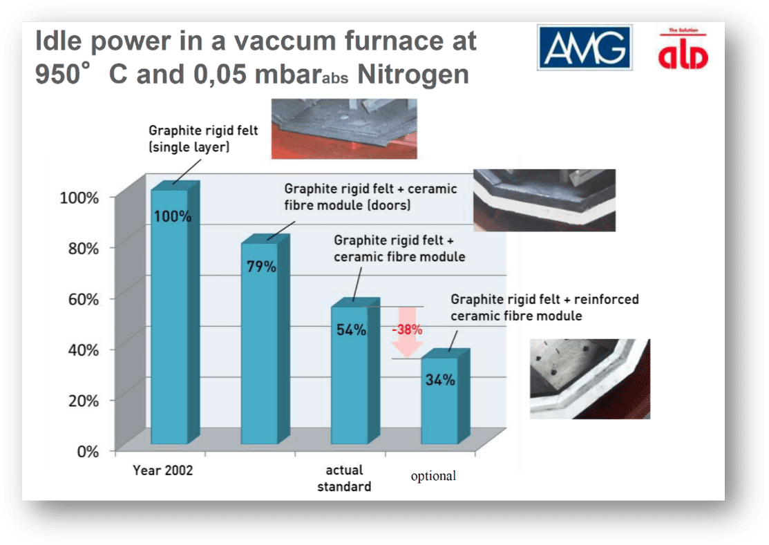
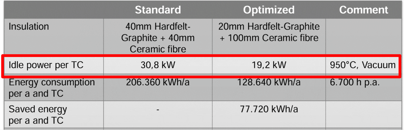
Fig. 15 – The development of the insulation of the heating chamber in ALD and the impact on the consumption of electrical energy during empty running [Gerald Hiller ALD, 2016, Istanbul]
But what are our options? It can be seen from Fig. 15 that the development and improvement of furnace insulation is experiencing a leap change. Compared to 2002, in the case of high-temperature furnaces, today we have 34% of the energy needed to maintain the temperature in an empty furnace (Idling Power).
Graphite insulation materials are continuously improved, using a larger insulation thickness, multi-layer, with a CFC surface to prevent external abrasion and with better emissivity. TAV uses the same insulation composition for its tempering and annealing furnaces as for the quenching furnaces. This has the result that the surface emissivity coefficient is constant, the thermal conductivity of the insulation is as good as in tempering furnaces, and all conditions for low energy consumption are therefore ensured
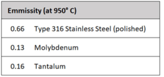
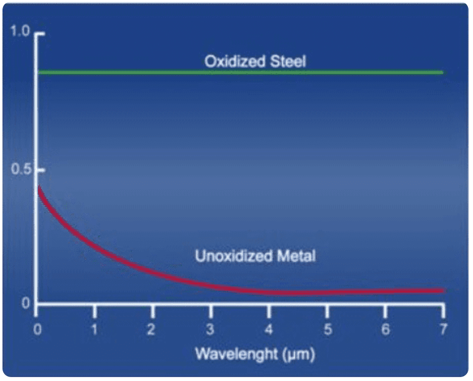
Fig. 16 and 17 – Surface emissivity of various materials and changes in emissivity due to oxidation [1]
If we have a furnace with a circulation insert made of carbon or stainless steel, we must expect that the emissivity will change with advancing oxidation. In furnaces with LPN, Inconel lining is used for internal protection of the insulation, with the ability of limited diffusion of nitrogen during nitriding, but even this material will tend to oxidize, especially since it is a process based on a mixture of NH3 and NO2.
For some aerospace applications, the heating chamber may be all-metal, molybdenum. Here, however, oxidation can be the biggest problem. If we need 50 to 60% of the installed power for a new furnace, due to oxidation we can get up to 90 to 100%. This is also why continuous measurement of consumption is important, it can show us the deteriorating condition of the furnace and the need for repair or replacement of elements.[1]
Graphite insulation will be stable from this point of view. Today it can take the form of graphite felt, rigid graphite board, coated, uncoated or with bonded films, mostly with a final layer of CFC. The only limitation of a furnace equipped in this way will be oxidation in water vapour. Subsequent furnace desorption would probably be almost impossible due to the complicated structure of graphite materials.
In addition to graphite insulation, mineral fibres are also used, either as a separate layer or in combination with graphite felt or board. A total insulation thickness of up to 80 mm is common today. In this way, an insulating layer can be modelled with minimal losses both by heat conduction and radiation from the heating elements. On the outside of the insulation, if it is properly designed, we get to a temperature below 200 °C for systems with a water-cooled jacket, or below 80 °C for chamber furnaces without water cooling.
When choosing insulation, it is also necessary to take into account their thermal capacity. This is the only disadvantage of graphite (Fig. 18). The insulation contains heat, which during heating takes part of the heat away from us to heat the charge, and when cooling, on the contrary, we have to remove this heat from the insulation. Since the cooling rate does not matter so much in tempering or annealing, it will not be a limit in this type of furnace.
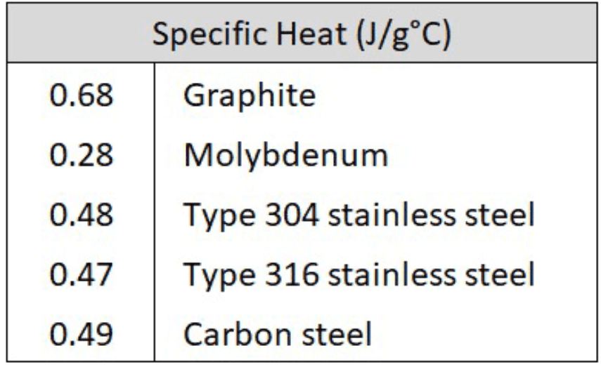
Fig. 18 – Heat capacity of different materials in the furnace [1]
So, what recommendations can we make when choosing a tempering and annealing furnace to improve the energy efficiency of our heat treatment?
If we really only perform these operations, not diffusion processes, then it is necessary to choose a furnace with direct heating, with heating elements inside the chamber. If we are already considering a hybrid device, i.e. including nitriding or nitrocarburizing, then we should first consider the route via LPN (Low Pressure Nitriding), where we do not lose the properties of direct heating. And if we are already considering the purchase of a hybrid device with atmospheric gas nitriding or nitrocarburizing, then we have to accept a significantly higher consumption of electricity for tempering or annealing processes due to the lost energy for heating and cooling the retort. It is usually heavier than the batch itself.
Is it negligible? The verified average hourly consumption of a 600x900x600 mm vacuum tempering furnace during the tempering cycle is 18 kW per hour, for a retort furnace of identical dimensions 23 kW. The saving is 5 kW per hour. At 80% plant utilization, the furnace is operating at 7,008 Nh per year. The saving per year is therefore 5 * 7,008 = 35,040 kWh. At today’s price of EUR 0,2/kWh, that is EUR 7 008 per year. For 20 years of using the furnace, with an inflationary load of energy prices of 5%, this will be a financial saving of EUR 231 726, an energy saving of 700,800 kWh, and a CO2 emission saving of 140 tons. Energy savings are therefore close to the purchase price of the equipment, the ecological impact is obvious.
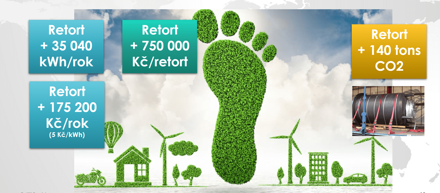
Fig. 19 – Cost difference between vacuum annealing and tempering furnace with direct heating and with retort
As I said at the beginning, the furnace supplier will not tell us the information about real consumption. It can be understood, if only partially. On the contrary, I would expect them to outdo each other in how efficient the device is to offer. However, this is not the case yet.
But the way out of it is not complicated. Every supplier has, or should have, a so-called FAT – Factory Acceptance Test. This means that we, the customers, have the right to request a test on our reference batch precisely for the purpose of verifying consumption. And here we will specify the furnace in the order. E.g. that 0.5 kWh/kg must be achieved on the reference batch.
With this, we simply establish the acceptance condition. If the supplier confirms it and subsequently fails to comply with the FAT, it can be taken as a breach of contract terms with all the consequences for the supplier.
[1] – https://www.linkedin.com/pulse/vacuum-furnace-hot-zones-metal-carbon-configurations-alan-charky/
Jiří Stanislav
August 25, 2024