Energy savings in commercial heat treatment II

So glory, we already have the measurements… we can proceed further.
For all types of furnaces, it is necessary to remember that we cannot influence the energy that we have to put into the charge to heat it up to the working temperature. This “technological consumption” will always be based on the heat capacity of the processed goods according to the formula Q = Cp * m * dT, where Cp = 0.6 kJ/kg for steel. But we can influence the energy effectively spent on this heating, and the energy lost.
In addition to “technological consumption“, there is also a parameter that we can call “technical consumption“. This is tied to the concept of the furnace, its energy balance and the amount of heat loss that this concept enables. Figure 1 shows a model of such a balance for a gas-fired multi-purpose furnace. The fact that everything is not quite right here stems from the fact that a full 30% of the total heat supplied to the furnace goes out, into the flue gas, without being used.
Of the remaining heating input, roughly 66% of the available energy goes into the batch itself, 16% is consumed by baskets and fixtures, and 14% is stored in the furnace wall. The rest are minor items.
But if we take into account the total supplied energy including flue gases, only 46% of the total supplied energy gets into the batch, 11% is consumed by baskets and fixtures and roughly 10% is stored in the furnace wall. Losses to water, heat radiation to the surroundings, or losses from opening the furnace door are not essential from the point of view of the energy balance.
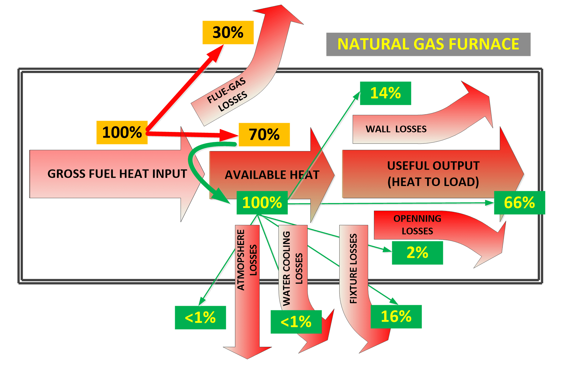
Fig. 1 – Heat balance of a gas-fired furnace (https://www.industrialheating.com/articles/92763-tools-to-boost-furnace-efficiency)
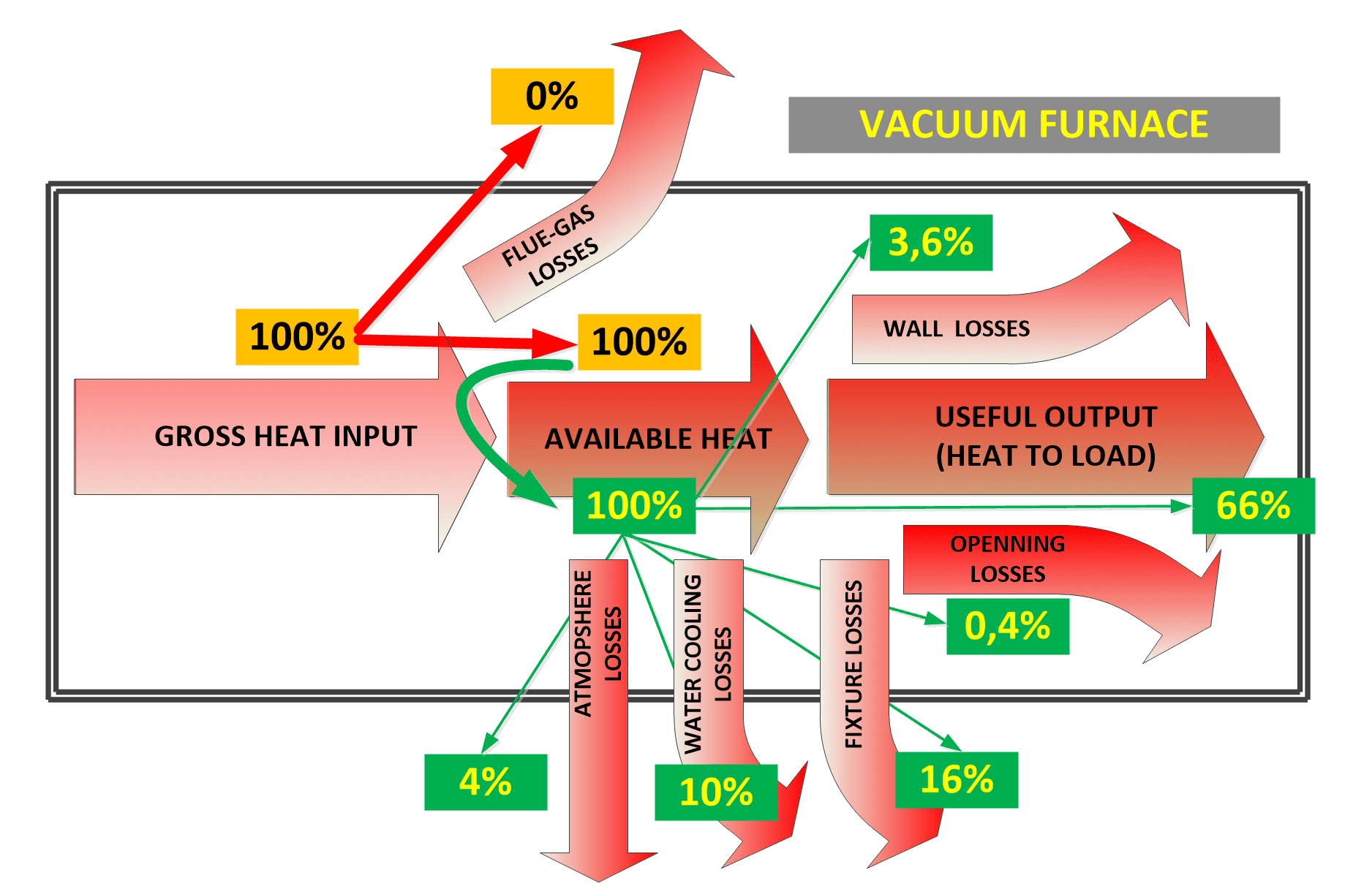
It is different with electrically heated furnaces, whether multipurpose or vacuum (Fig. 2). Since there is no combustion process, 100% of the input energy can be considered as available energy. Even though we get 66% of the heat output in the batch again, this percentage evaluation is the final value. Compared to 46% from a gas-fired furnace, this is a 20% better efficiency of the overall delivered heat. In contrast, the share of energy required for heating the baskets and fixtures is again 16%, but this is a final value that indicates a higher sensitivity of the efficiency of the process in an electrically heated furnace with regard to the weight of the baskets and fixures and preparations or the insulation of the heating chamber. A significant outflow of heat energy is also transferred to water and the cooling system.
Technical consumption is therefore strongly tied to losses, and will be significantly influenced by the concept of the furnace, its technical condition, the quality of insulation and other factors related to innovations or equipment maintenance. This is also why the role of statistically evaluable measurement of energy consumption per batch is important, because during repeated processes we can evaluate these data with regard to preventive or predictive maintenance. It is precisely the change in energy consumption that can indicate problems with the technical condition of the furnace.
In all cases, however, it is also necessary to consider how to effectively transfer the supplied heat to the charge. The concept of multi-purpose muffle furnaces or vacuum retort furnaces on the one hand takes part of the input energy for heating the muffle or retort, on the other hand does not allow direct heating of the charge. This takes place indirectly through the flowing protective atmosphere by forced convection or radiation from the walls of the muffle or retort. Part of the energy, whether in gas or electrically heated furnaces, will therefore be used to heat muffles or retorts.
The following graph in Figure 3 is a comparison of the unit consumption in kWh/kg for a vacuum tempering furnace with indirect electric heating and and retort, and for tempering furnaces with direct electric heating. It can be seen from the graph that the difference in consumption, especially for lower batch weights, is 30%. The unit consumption curves have an exponential character. With a more economically advantageous furnace weight load, the so-called JobFillRate%, this difference gradually decreases, but for real batch weights it never disappears. But if we want to go below our magic value of 1kWh/kg, then with a furnace with direct heating we need a charge of 120 kg, while with a retort furnace we have an economic charge of up to around 200 kg, i.e. 67% higher. Our second magic limit of 0.5 kWh/kg can be reached with a furnace with direct heating with a charge of around 250 kg, and with a retort solution around 450 kg, which is already 80% more.
The same rules will also apply to high-temperature furnaces, only the differences will be smaller considering that the muffle or retort will be at a temperature above 800 C and heat transfer by radiation will be more efficient.
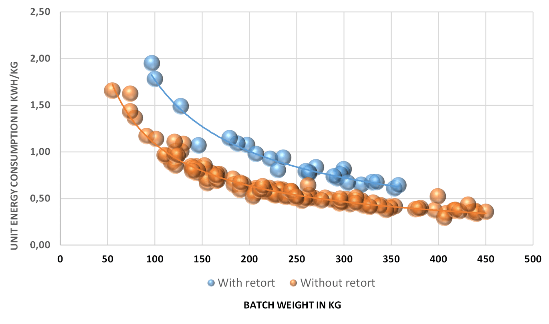
Fig. 3 – Comparison of unit energy consumption for tempering for retort and direct heating furnace
Indirect heating via a retort or muffle has yet another pitfall. In the next Figure 4, the possible states of regulation during the rise to temperature are shown.
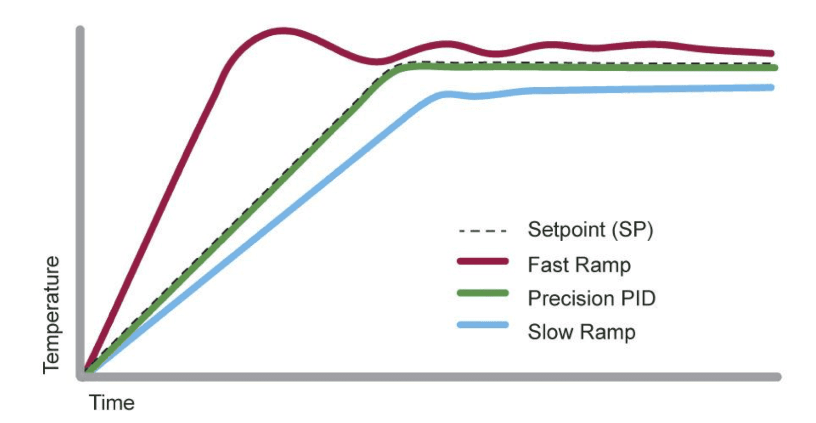
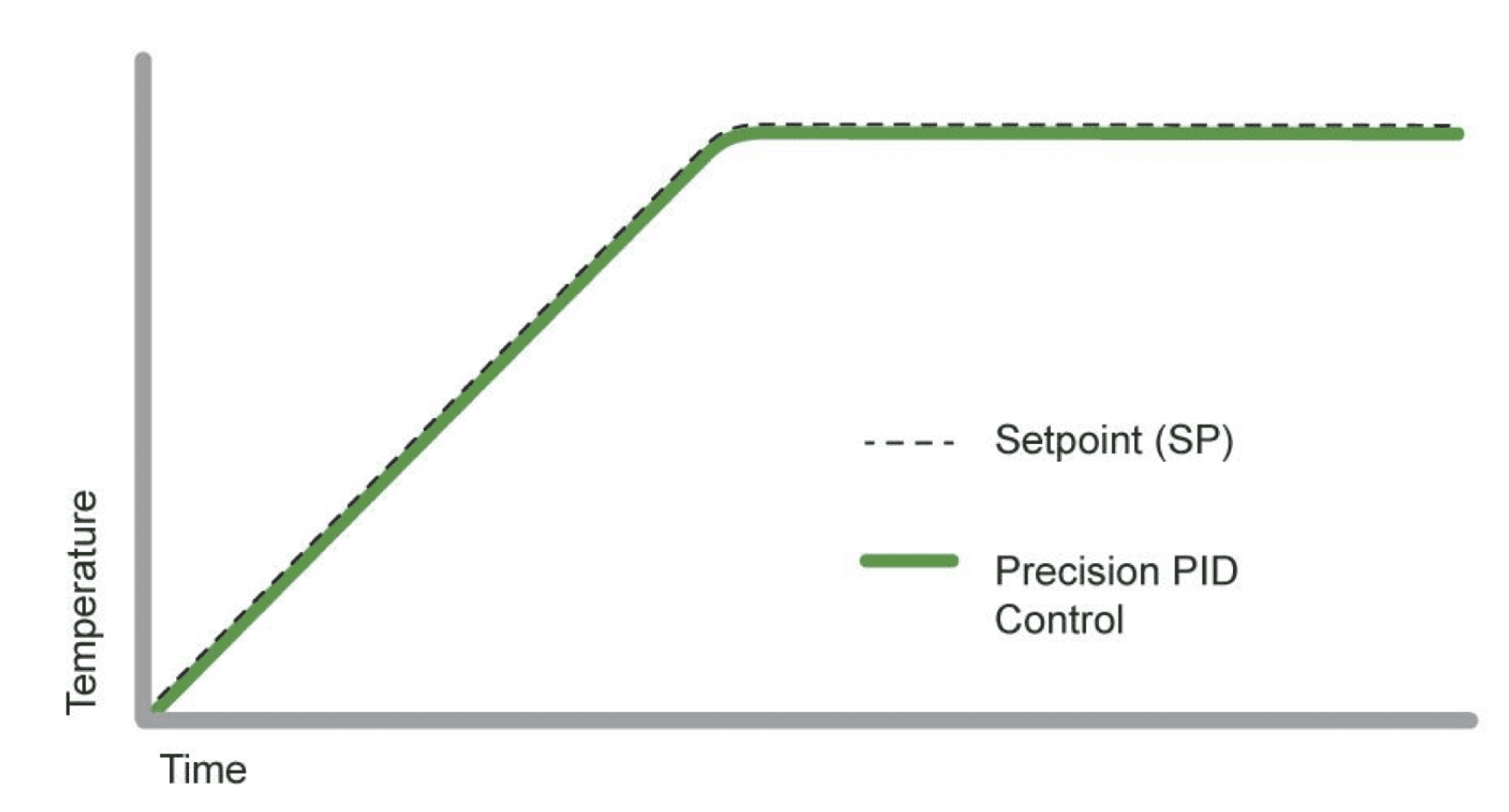
Fig. 4 – The problem of temperature regulation with regard to the intelligence of regulator
If we do not have perfect regulation, then not only does the system regulate to a temperature outside our setpoint, but in the event of overheating, it is also wasted energy or an extension of the process time with the same impact on consumption. However, since heat treatment furnaces operate in a variable temperature regime, the conditions in the furnace in terms of radiation or convection also change during heating. Even if the temperature controller will have a so-called self-learning function, the problem will always be that a different set of PID constants is needed in each temperature range. But not every regulator can do that.
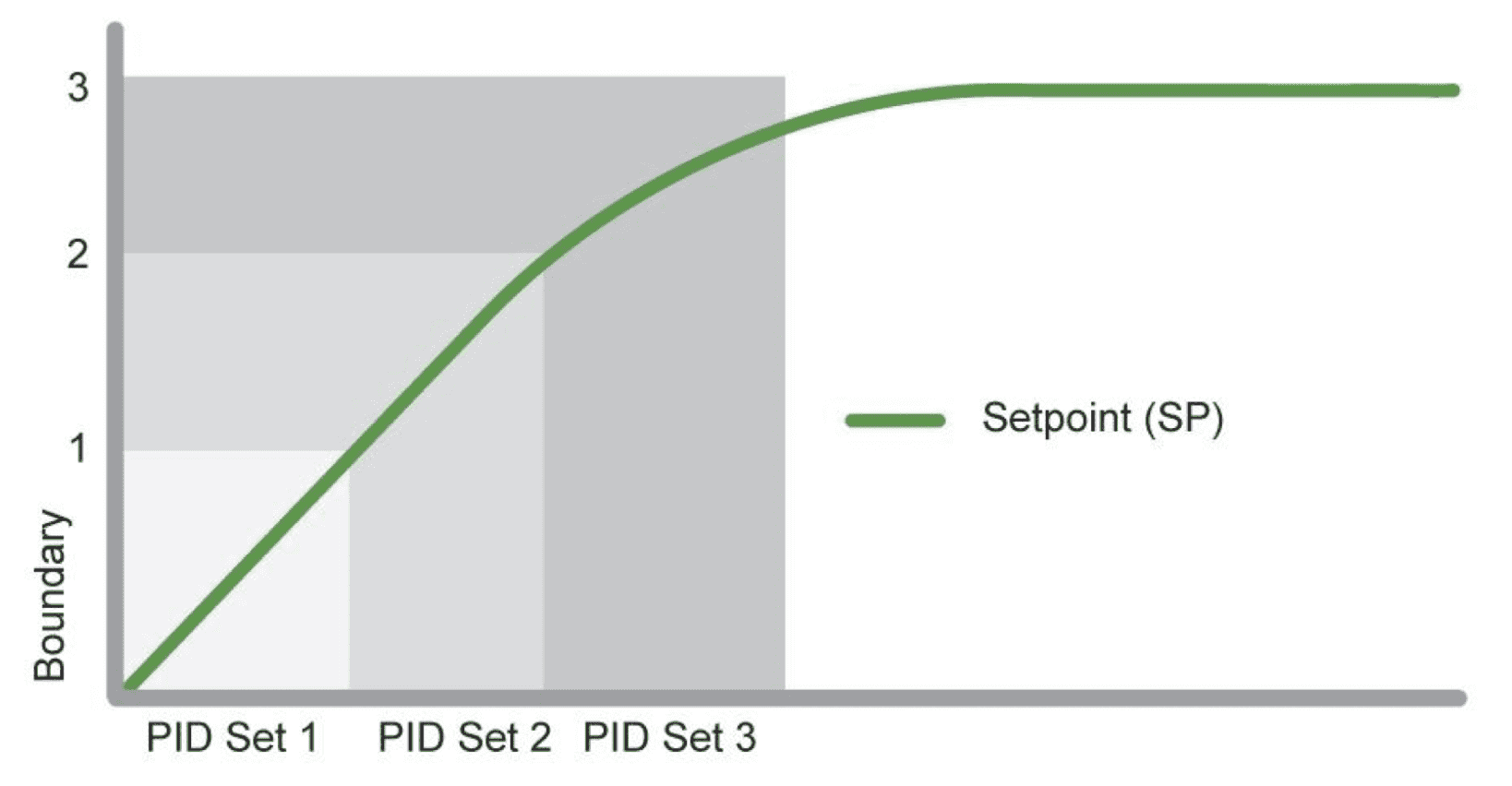
Fig. 5 – Precise temperature control with variable PID values
Another problem is that the change in heating conditions in the retort solution of the furnace is also linked to the weight of the charge, i.e. to the time response of the device, which is different for each cycle. If we set the PID constants for one batch, they may not apply to the other. This can be seen in the records of tempering processes from the retort furnace in Figure 6. The behaviour of the furnace temperature control at large batch is optimal. But this does not apply to a small batch weighing 96 kg. Not only will our unit consumption be high due to the low JobFillRate%, but we will also be consuming useless energy as the furnace overheats above the set SP. I’m not even talking about the technological impact on the result here.
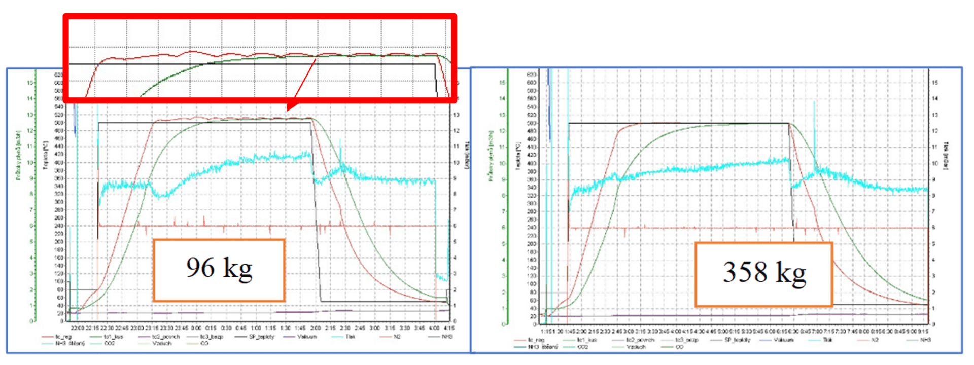
Fig. 6 – Comparison of retort furnace behavior for small and large batches
So what should we focus on from a “technical consumption” perspective? If possible, above all for innovation and investment. Not everything can be reconstructed to new conditions. Just as we will not turn a car with a diesel engine into an electric car, we will not turn an old furnace into a low-energy furnace either. And since we usually depreciate furnaces over 20 years, we have to make these considerations from the point of view of this time horizon as well.
So in summary:
- In terms of energy consumption, we must choose the solution that gives the lowest values for the above-mentioned time period. We should calibrate to a target of <1 kWh/kg for high-temperature processes such as quenching or cementation, and values of <0.5 kWh/kg for low-temperature processes
- From the point of view of emissions, we must choose the solution that will take into account the forecast of the energy mix for the entire lifetime of the furnace. This forecast says that in the Czech Republic it will be 50 – 90 gCO2/kWh in 2040.
Not many solutions follow from these two conditions. In the event that the energy mix falls with its emissions below the level of 220 gCO2/kWh, the only possible solution in terms of emissions will be an electrically heated furnace. And if we want to achieve the first criterion, i.e. <1 kWh/kg, then we have to lean towards a vacuum solution. But even that has its pitfalls. If we make a simple consideration of the energy demand of heat treatment for hardening or carburizing, then we can see that if we want to get below 1 kWh/kg with energy consumption, we have to choose a two-chamber or multi-chamber vacuum furnace solution or go significantly higher with the average batch weights (Fig. 7).
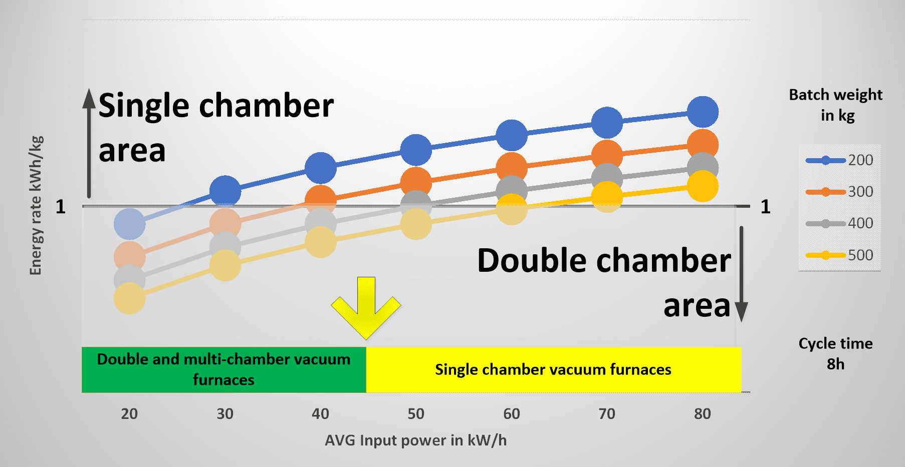
Fig. 7 – Energy demand = average energy input of the furnace in kWh * average cycle time of 8 hours / batch weight
The graph shows us under what conditions we can reach the target of <1 kWh/kg. Since single-chamber vacuum furnaces show an average hourly consumption of 45-80 kWh during the working cycle, measured from closing to opening of the furnace door, it can be seen that with single-chamber furnaces we can reach the region of <1 kWh/kg only with batch of 400 kg and more.
So, in order to get to the area, we want more easily, we need furnaces where the average hourly consumption will be around 30-40 kWh, including the quenching period. In the link below is an ALD presentation by Gerald Hiller on the ALD Multi chamber system. This is a solution where the heating and carburizing process takes place in several identical heating chambers, and the quenching process takes place in a mobile quenching module with an overpressure of N2 or He up to 20 bar. The working chambers are permanently maintained at a temperature, and as stated in the presentation, in terms of unit consumption, we reach values of around 0,3 kWh/kg. However, the energy required for cooling in the mobile quenching module is not taken into account in the calculation. So overall, we will be approaching our magic limit of 0.5 kWh/kg.
A similar situation will be with two-chamber furnaces with oil hardening, because here, as with the multi-chamber solution, we have a permanently heated heating chamber. As this type of furnace, unlike multi-purpose furnaces, has neither a retort nor a muffle, the supplied energy will only be used for heating the wall and for heating the charge including the baskets and fixtures. The lost energy will therefore depend only on the quality of the insulation of the heating chamber or the weight of the baskets and fixtures, and even here significant technical progress can be seen (Fig. 8). Overall, as stated in the presentation, we can reach a maintenance power of 19 kW without batch, which is power that covers only the losses of the heating chamber. In practice, however, for multi-purpose furnaces, whether heated with gas or electricity, the values are 2 to 3 times higher.
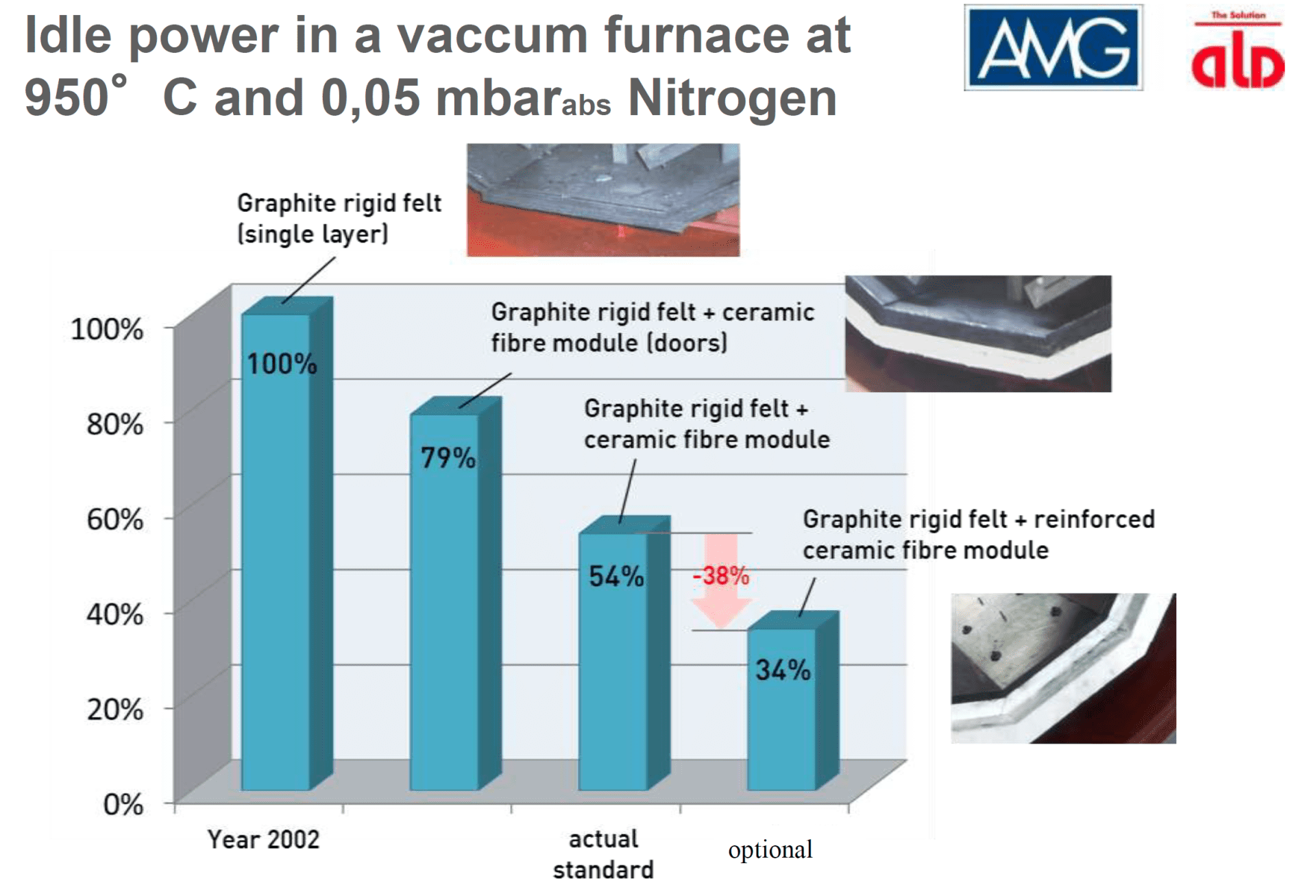
Fig. 8 – Development of insulating materials and their combination for the efficiency of vacuum furnaces
Compared to the single-chamber solution of the vacuum furnace, the two- or multi-chamber solution has a single disadvantage, identical to multi-purpose furnaces. Since the batch moves from one chamber to another in the furnace, we cannot work with batch thermocouples. Perhaps this is also the reason why single-chamber vacuum furnaces still have priority over multi-chamber systems.
Personally, I also consider it a big disadvantage. Both from the point of view of the accuracy of the technological management of the process, but above all also from the point of view of energy consumption. After all, the impossibility of using batch thermocouples leads to the empirical determination of some cycle parameters, and we know well from practice that theory often differs greatly from practice.
A partial solution is a data logger with a Bluetooth output signal, where the own sensing device can travel with the batch and temperature data is wirelessly sent outside the furnace (Fig. 9). Although this instrument is primarily intended for TUS measurement, it is also conceivable to use it for modelling and controlling the temperature in the batch, including the quenching phase in the gas stream. However, its use when quenching in oil will be problematic. But what prevents its use above all is the possibility of the device staying at the working temperature for only a limited time, and even then, in an insulated box, the dimensions of which grow significantly as the temperature of use increases.
If a path to miniaturization could be found, or to increase the temperature resistance of the device, then it would represent a revolutionary solution in heat treatment.

Fig. 9 – An example of a Phoenix data logger with Bluetooth output
So what investment strategy to choose for the future?
- The vacuum solution will have priority over classic furnaces with a protective atmosphere
- Since the large appliances of the heat treatment plant will gradually be burdened with ecological and energy tax within the framework of FIT55, they should definitely be electrically heated furnaces
- Single-chamber vacuum furnaces will continue to maintain their place for heat treatment, but there will be pressure to increase their efficiency through better insulation, more intelligent temperature control or reducing the weight of products
- The trend will be two- and multi-chamber systems. Not only for clearly lower energy requirements, but also for high process flexibility. With multi-purpose furnaces today, it is difficult to imagine the heat treatment of tool steels, or even soldering, for a vacuum solution this is the logical outcome of the state of the art (Fig. 10, 12)
- Since, historically, a still significant part of heat treatment is carried out in shaft furnaces, they too will have a solution with LPC and oil quenching (Fig. no. 13)
- If we consider energy requirements for single-chamber vacuum furnaces, we will be somewhere around 1 kW/Kg for hardening, but for two-chamber and multi-chamber ones it will be up to 50% lower
- Since full automation of operation is already a matter of course for multi-purpose lines, the same awaits us with the vacuum solution. In order for this to be feasible, we will have to get rid of the classically open chamber door and switch to a horizontal or vertical entrance door solution (Fig. no. 11)
- Low-pressure carburizing, despite the continuing technological difficulties, has priority over classic processes for the future, primarily due to energy savings. It makes it possible to switch from various muffle or retort furnace concepts to direct heating solutions. The higher the requirement for CHD, the more energy savings low-pressure cementation offers (Fig. no. 14)
- It goes without saying that each furnace must be mandatorily equipped with consumption meters, and these data must be assignable to the batch. Furnace control systems must therefore have higher intelligence, enabling the evaluation of economic processing parameters either directly or by connecting to the ERP system, and must not focus only on temperature control. For autonomous systems not connected to ERP, we will also need to measure operating hours, idle hours or shutdown times so that we are able to report the time and energy use of the furnace.
- If we want to temper effectively, then only furnaces with direct heating and without a retort can be recommended. Otherwise, we incur unnecessary costs in each process to heat the retort and cool it down. We will leave this type of furnace for use in chemical-thermal processing such as nitriding or nitrocarburizing, where the above-mentioned shortcoming is eliminated by the fact that these are single-step processes, with long processing times, and therefore the influence of heating and cooling of the retort decreases to a bearable level.
- We will not have to get used to tempering in quenching furnaces, they are not designed for this nor are they operationally economical enough for this purpose.
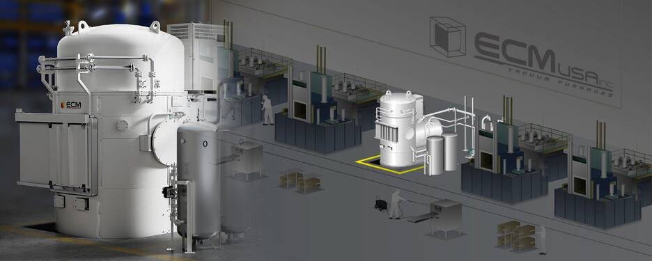
Fig. 10 – An example of a line of multi-purpose furnaces in combination with low-pressure carburizing ECM Eco Duo
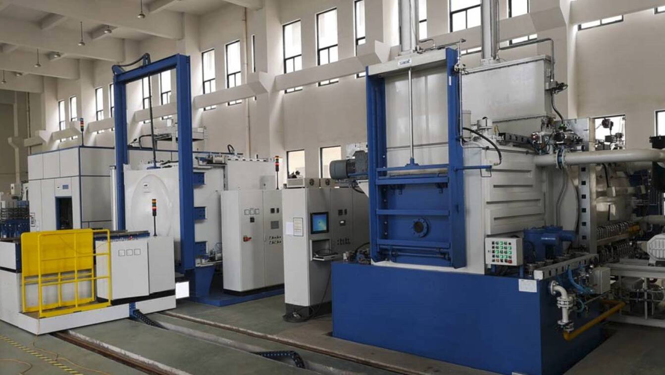
Fig. 11 – An example of a line with low-pressure carburizing and hardening in oil from SAMT Shanghai
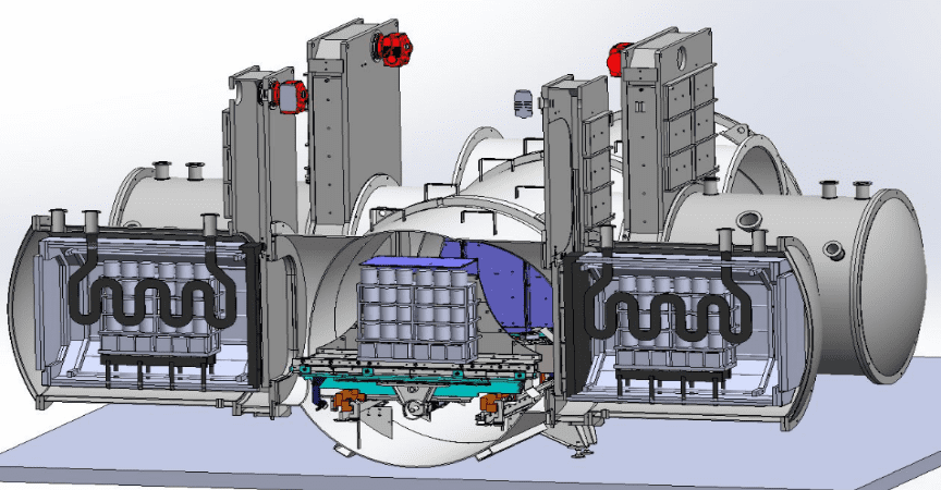
Fig. 12 – The flexibility of the vacuum solution makes it possible to carburize, harden tool steels or even braze within one furnace (multi-chamber ECM Flex solution)
Fig. 13 – ECM PFTH bell furnace for LPC with oil quenching, dia 1500 mm x 1500 mm, batch weight up to 1500 kg
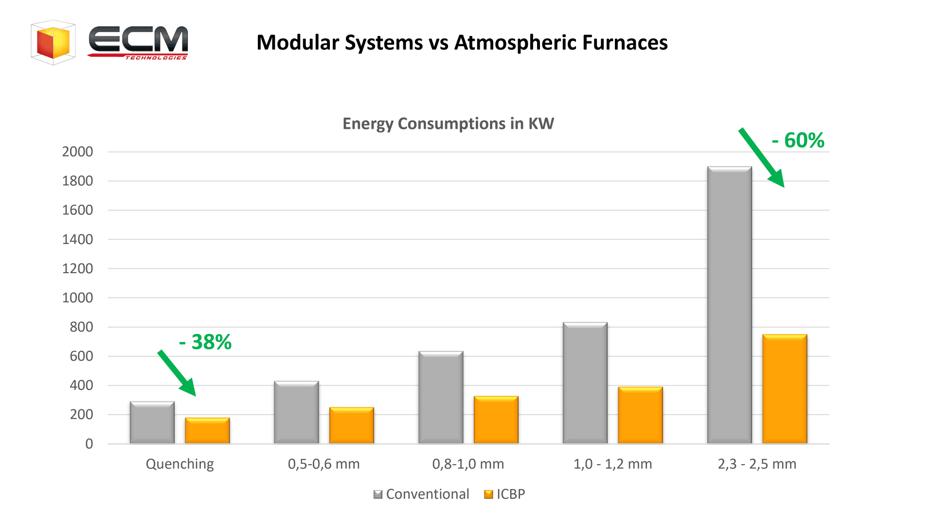
Fig. 14 – Energy savings for individual technologies in a modular system from ECM
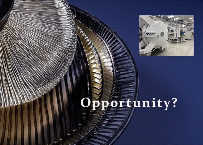
Of course, the above facts must be taken as a recommendation. There will certainly be exceptions. Not so long ago, however, my friend Janusz Kowalewski asked me, after visiting an aerospace heat treatment plant in Asia, what arguments to use for a customer to buy a single-chamber quenching vacuum furnace with an overpressure of 6 bar, when the existing processes are carried out in a two-chamber furnace, even though with an overpressure of 1.5 bar. And he surprisingly adds, they only have two-chamber ovens here!!
What to say to that? The fact that Asia is already switching to two or more chamber solutions is just a confirmation of the above. And if the customer really wanted to improve the processes, then the only logical outcome of his problem is again a two-chamber solution, only the hardening capacity of the furnace must be increased to 6 bar.
So, up to energy innovation.
January 16, 2023
Jiří Stanislav

